Smart Fan 1.0
As noted over in the User-configurable delays post, I'm starting into some "home automation" type projects, specifically for some things around the property for PEACE. The overall focus is on small "quality of life" improvements for things we do frequently or repeatedly, and that make it easier to ensure comfortable and safe spaces for the sanctuary residents.
The first of those is fans in the residents' enclosures. I'll walk through that here.
Background and motivation
In all of the sanctuary residents' enclosures, we have some fairly basic 90W fans to help keep things a bit cooler on hot days. These are 3-speed pull chain units like these ones from Vevor or "Deluxe" (both seem to have the same internals):
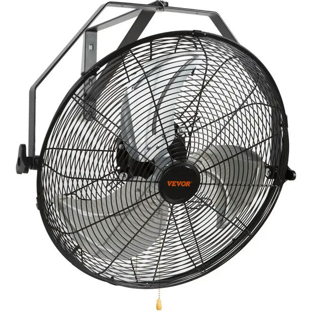
Vevor 90W 3-speed pull chain fan
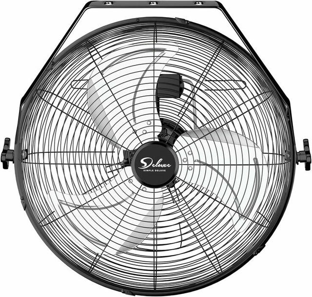
'Deluxe' brand 90W 3-speed pull chain fan
During the warmer seasons, we keep an eye on the temperature and then adjust the fans as needed to give the residents a space to cool off. There are a few variables here, though.
The enclosures that are up-field are purely on the off-grid solar setup up there. This means limited reserve energy storage that needs to be managed. That's generally not an issue if things are hot out, as that's going to correlate with "lots of sunshine," but we do need to keep an eye on things clouding over. We ideally also slow or shut off the fans as the sun ducks behind the mountainside later in the day and things cool off, but before we come up for evening chores to get everyone inside, both given that blowing the fans full tilt as it's already cooled off is pointless, and also because the sun tucking behind the mountainside means that the solar energy generation drops off. That's not the end of the world, but 180W running for a couple of hours is still 360 Wh of the 2,400 Wh energy budget in the batteries.
The enclosures themselves are a couple hundred meters up an incline:

A satellite view of the PEACE Sanctuary location, showing the animal enclosures on the left, up a slope from the main buildings
...which can be a pretty solid walk on a hot day!
Overall, rather than having to try to balance out "how hot will it get today" versus an energy budget, or otherwise walking several hundred meters back and forth potentially in schorching heat to adjust things as needed, the ideal would be if the fans could just respond automatically to temperature changes, as well as being able to take the solar input and battery state into account to ensure we don't run out our energy reserve in the batteries.
Fortunately, with help from ESPHome, we could achieve exactly that!
Off the bat I want to give credit to 3ative's Ultimate Fan Project v4.0 as basically the foundation of this project, with modifications away from their desktop fan design to the pull-chain option I used here.
Hardware
To make the fan "smart," we need:
- The fan itself (Amazon links: Vevor 18" fan, Deluxe 18" fan)
- 4-relay ESP32 board (AliExpress)
- Momentary push button (AliExpress)
- Temperature sensor (AliExpress) and 4.7 kΩ resistor (AliExpress))
- Case
Fair warning: this project does require a chunk of rewiring, and there is soldering involved at a few different places.
The fans
The 18" fans seem to have been replaced somewhat. You can still buy the Vevor 18" unit, but it's now over $200 and replaced with oscillating units instead. The Deluxe 18" unit is now also over $200, while the 20" unit is around the price the 18" was previously, just over $100. The 20" fans appear to be 130W units rather than the 90W of the 18" models we have. We haven't bought any of the 20" units yet, so I can't confirm the exact internals, but as long as things are broadly the same things should translate to work the same on those units.
The board
These are all over AliExpress, and some on Amazon as well. The key things that make this project simpler here are:
- Integrated ESP32
- Mains powered
You can opt to just buy a "dumb" 4-relay board and slap an ESP32 or other microcontroller on separate to it, or find boards that require separate 5V DC power, but getting the integrated unit really makes things a lot simpler.
Temperature probe and resistor
I ended up sweating this (hah!) a lot, probably more than I needed to, and ultimately settled on just a simple DS18B20 sensor. There are some tradeoffs here as:
- it's not super accurate
- it requires an external resistor
...but, it is very easily picked up in an enclosed unit (stainless steel "barrel" design) that is important for the dusty spaces where we're installing these, and I could work around the other items.
I would have probably liked to go with something a bit more accurate like a Sensirion SHT41, but I couldn't easily track down an enclosed unit for that.
For the resistor: You can alternatively also pick up a DS2484 that simplifies the wiring for you a bit, but the resistor route was workable for me.
The case
The board itself is 93mm x 87mm. Before receiving the board, the only reference I could find before actually having the board in hand was a Cirkit Designer link that claimed it was 100mm x 70mm x 20mm, and I ordered a case to fit that. However, on receiving it, those dimensions were obviously off and the case was too small.
To fit the unit, I ended up only finding something oversized (lots of spare room, far too tall) on Amazon at 160mm x 160mm x 90mm. You do need to leave a bit of extra room to allow space for the push button, but this is overkill.
Ultimately I did find some 3D print models online afterwards that should do the trick, e.g. this one. For subsequent units I'll be going that route, as I fortunately have a friend that's willing to do some 3D prints for me!
If you go that route, just bear in mind that a lot of the 3D print designs are quite shallow, opting to wrap quite closely around the board and likely making it a tight squeeze to fit extra pieces like the push button.
Miscellaneous
Depending on which case you select, you may also need some stand offs for mounting the board. I used this set from Amazon. I also opted for ferrules on the wiring for the relay, for which I used these from AliExpress.
You'll need some hookup wire for the button and temperature sensor, as well as a bit of mains wire (14 gauge).
I picked up an excellent Pinecil soldering iron recently, but whatever works for you.
The code!
After the hardware, we still need some software to make it go!
If you want to get straight into it, my ESPHome code for the example unit is on Codeberg.
The first unit is for the pigs' enclosure, so it's the "Piggie Pals" location. Just replace the references to "Piggie Pals" with what you need. I'll not copy paste it all here, but will walk through the code in sections further down.
The theory
At the back of the fan is a small box just below the motor housing. This holds the "guts" of the unit that we're concerned with replacing. Specifically, there is a a capacitor and a ZE-268S1 switch:
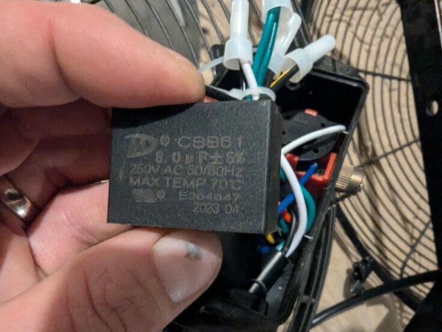
The CBB61 capacitor from the fan
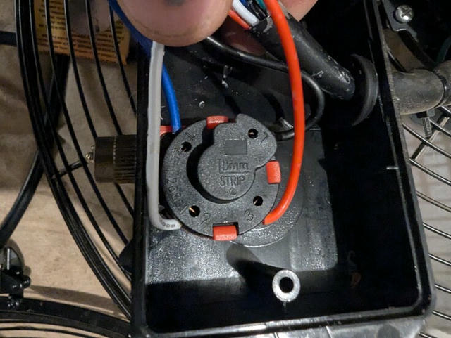
The ZE-268S1 pull chain switch from the fan
Importantly: The capacitor stays. We will only be replacing the pull chain switch.
Fortunately for us, the ZE-268S1 switch has a fairly simple setup:
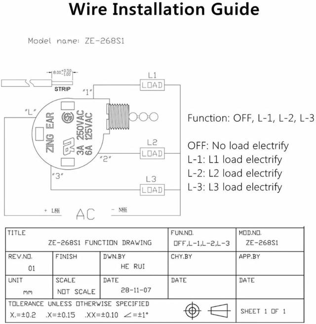
Schematic for the ZE-268S1 switch
The pull chain just moves the switch from no connection to L1, then L2, then L3, corresponding to speeds 1, 2, and 3 on the fan.
This is where our relay comes in!
Rather than using the pull chain switch, we will hook up our relay board so relay 1 goes to the L1 position, relay 2 to L2, and relay 3 to L3. So when we throw relay 1, the fan runs at speed 1, etc.
Wire it up
For the primary bit of wiring on the relay board itself, I absolutely encourage you to to look at the Youtube tutorial guide 3ative put together, as honestly I can't beat the work they put into that. The bit for wiring up the mains and specifically the common to the board starts at around 23:03.
Basically, the build process for me was:
- start with 3ative's guide
- skip the bits about the push buttons and LEDs entirely
- skip the "party mode" random thing entirely
- add a single momentary push button instead of their 3 separate buttons and LEDs
- add the temperature sensor
- add a good chunk of ESPHome code for those pieces and the temperature-based control
As I don't think I can improve on 3native's guide, I'll leave y'all to do 1 and I'll focus on 4-6.
Push button installation
We'll use a regular GPIO pin for the push button. Note that pins 25, 26, 32, and 33 are in use for the 4 relays, so those are not available for our general use. That's indicated in lines 134-167 of the ESPHome code.
For our project, I wired the button to pin 27 (next up after the relay at 26), wiring the other end to one of the grounds on the board. Completing the wiring to ESP pins becomes a bit tricky here at times as the pin numbering is only visible on the bottom of the board, so it takes some care to ensure you're connecting things up correctly:

Underside of ESP32 4-relay board", alt="Underside of the ESP32 4-relay board, showing the ESP32 pin locations
At any rate: One side of the button to GPIO 27; the other to GND (in my case at the top next to the 3V3 pin).
We'll get into more details of the code further below, but the basics for the button are lines 102-113:
binary_sensor:
  - platform: gpio
    name: Button Sensor
    id: button1_sensor
    pin:
      number: 27
      inverted: True
      mode:
        input: True
        pullup: True
    filters:
      - delayed_on_off: 10ms
We're setting pullup: True here as we're wiring the one leg of the button to ground.
Temperature sensor
This takes a bit more work. As noted above, the DS18B20 temperature sensor needs a 4.7 kΩ resistor installed. This tutorial does a good job of describing the layout. I'm using the "normal mode" they describe (I won't be using GPIO4 here, but just using this image for general reference), e.g.:
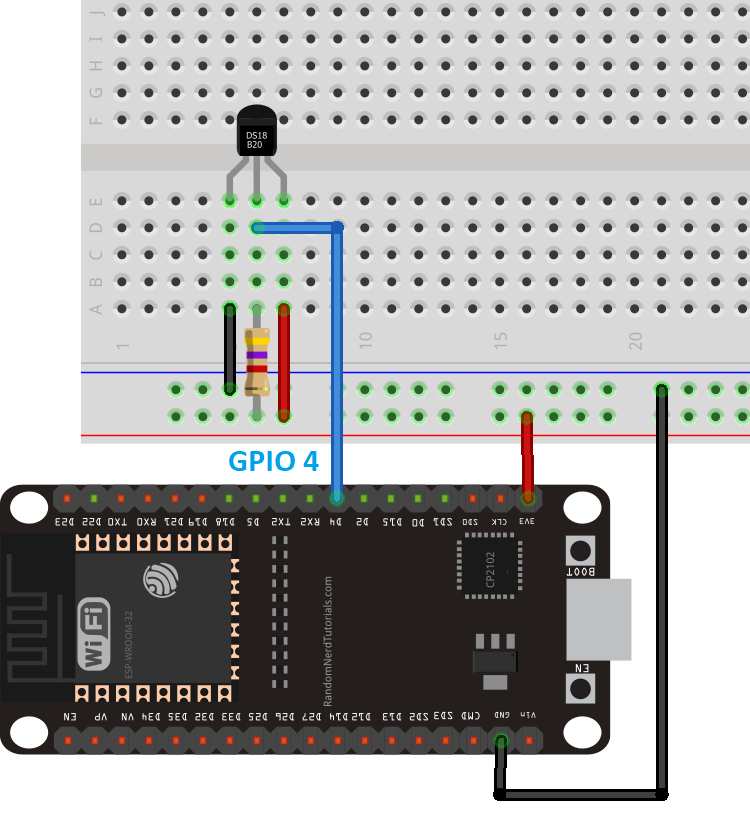
Wiring for the DS18B20 temperature sensor
The gist is that you need:
- A 3.3V feed to VCC (red wire)
- Ground to the black wire
- One end of the resistor to your 3.3V
- The other end of the resistor connected to your line between your GPIO and the sensor's data line (blue)
Shown differently, something like this:
Schematic layout for DS18B20 sensor wiring with resistor
Which, like, sure: that's great, but that's still a little theoretical.
Now, I was silly and failed to take an actual photo of this properly, but in practice, you can:
- Connect the VCC wire of the temp sensor (red wire) to one leg of the resistor
- Connect the data wire of the temp sensor (blue wire) to the other leg of the resistor
- Wire the VCC-coupled leg of the resistor (the one with the red wire) to your 3.3V
- Wire the other leg of the resistor (the one with the blue wire) to your GPIO pin (we'll be using pin 14)
It's a small difference in the depiction, but I find that the visual helps:
Schematic layout for DS18B20 sensor wiring with resistor, focusing on the resistor wiring
Code walkthrough
As mentioned above, my ESPHome code for this is on Codeberg. I'll also refer again to 3ative's Github repo for their Ultimate Fan Project, as that forms the basis and vast majority of the code for this.
That said, I'll walk through the adjustments and tweaks I made here. If you want to get deeper into the configurable timers, I have a separate post about that at User-configurable delays in ESPHome.
Boilerplate
This is basically everything up to and including the wifi section, so lines 1-53.
There are only really a few key pieces here.
esphome:
  # ...
  on_boot:
    then:
      - delay: 10s
      - wifi.enable:
# ...
wifi:
  #### Disable WiFi on boot to allow local automations to run without waiting for WiFi to connect ####
  enable_on_boot: false
We set wifi.enable_on_boot to false so that we don't block on any local automation in case we are unable to connect to wifi, then we set a 10s delay to enable wifi afterwards. A key objective for the project is to be able to work fully offline, and this is in service of that objective.
The temp_sensor_address we will get to below.
I also explicitly enable mdns (not really necessary as it's enabled by default, but 🤷), and also enable IPv6, though that obviously is up to you for whether it's appropriate for your environment (though I do encourage IPv6 adoption 😉):
mdns:
  disabled: false

network:
  enable_ipv6: true
  min_ipv6_addr_count: 2
Temperature sensor
We use the ESPHome dallas_temp component for the DS18B20 temperature sensor, which in turn requires the uses the Dallas one_wire component for its Dallas 1-Wire protocol configuration.
We'll break this down bit-by-bit
one_wire:
  - platform: gpio
    pin: 14
    id: onewire_bus1
# ...
This sets up a 1-Wire bus on GPIO14 and assigns it an ID of onewire_bus1. Technically we don't need an ID if we're only going to have a single 1-Wire bus, but I prefer to be explicit. We'll refer to this bus below when we set up the actual temperature sensor.
sensor:
  # ...
  - platform: dallas_temp
    address: ${temp_sensor_address}
    name: "Temperature"
    id: temperature
    update_interval: 60s
    one_wire_id: onewire_bus1
    unit_of_measurement: "°C"
    device_class: "temperature"
    state_class: "measurement"
    accuracy_decimals: 1
    filters:
      - sliding_window_moving_average:
          window_size: 10
          send_every: 1
This is the main temperature sensor setup.
Per the Obtaining Sensor IDs section in the ESPHome docs, you will need to first start up your ESPHome device with the one_wire bus configured as well as the DS18B20 sensor connected in order to read its ID from the logs. Record that address and set it as the value for the temp_sensor_address in the substitions heading at the beginning of the file, which is then referred to here under the address.
Name is the friendly name that will show up in Home Assistant. id can be referred to elsewhere in the code, though ultimately we trigger off of this sensor and don't need to refer to it in any of our other configuration.
The update_interval here plays into the sliding_window_moving_average filter. I found that the cheaper sensors I picked up are somewhat "twitchy" and variable. For the purposes of controlling the fan speed we don't need the temperature change to be super immediate, but we do want it to not be jumpy to trigger frequent fan speed changes. We use a sliding_window_moving_average to help smooth that out.
To see what I mean by "twitchy", compare this temperature reading from the DS18B20 sensor out of the box with an Acurite 606TX sensor out of the box:
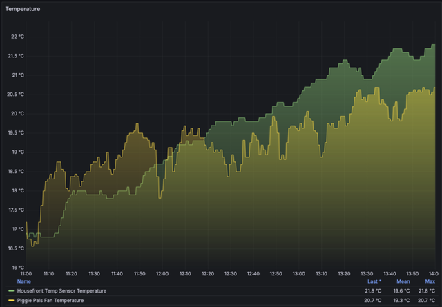
DS18B20 in yellow, Acurite 606TX in green
Note that the absolute values here are expected to be different, as the sensors are in different areas, where the DS18B20 location is expected to warm up earlier in the day.
Compare that with the same time period on a different day, after applying the sliding_window_moving_average above to the DS18B20 sensor reading (the Acurite 606TX still has no filtering applied):
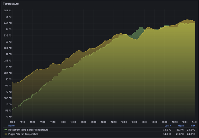
DS18B20 in yellow, Acurite 606TX in green
It's still not quite as consistent, but definitely a lot less twitchy.
Moving on!
The one_wire_id refers to the onewire_bus1 bus we defined above.
unit_of_measurement here is fairly obvious.
device_class set to temperature ensures the sensor is picked up properly by Home Assistant as a temperature reading, per Device class.
Setting state_class to "measurement" ensures that Home Assistant will collect long term statistics for the sensor values and be able to display them in a statistics history graph. This isn't strictly necessary, but nice to have.
And finally, accuracy_decimals here is also fairly self-explanatory.
There is one setting that I have not bothered to define, which is resolution. From the Home Assistant component docs for dallas_temp:
An optional resolution from 9 to 12. Higher means more accurate. Defaults to the maximum for most Dallas temperature sensors: 12.
The exact details of what the resolution value changes, i.e. how it adjusts the temperature readings, is not clearly spelled out. From the datasheet, though:
The resolution of the temperature sensor is user-configurable to 9, 10, 11, or 12 bits, corresponding to increments of 0.5°C, 0.25°C, 0.125°C, and 0.0625°C, respectively.
So note: the resolution does not correspond directly to the number of decimals in the reading, for instance. Given that we're applying smoothing with a moving average window, super high resolution probably isn't really going to matter too much one way or the other, but changing it from the default doesn't seem to really net any benefit regardless.
The actual temperature control
The above is really just the basics of the sensors and the button. The fun stuff is in the actual fan speed control.
This has a good number of moving parts, so I'll try to build this up somehow from the basic control and then run through the reasoning of the various bits as they get added.
The very basics
First off, we need something to move through the fan speeds. The basic platform: gpio switches in lines 134-167 are enough to have toggles show up in Home Assistant to control to relays to set the speed, but we can make that cleaner.
To handle that we create a template number. In short, this gives us a slider to move the number from 0 through to 3, for "off" and then through the 3 speeds. That looks like this:
number:
  ## Slider for Home Assistant and Fan Speed Control ##
  - platform: template
    name: Speed
    id: fanspeed
    icon: mdi:weather-windy
    update_interval: never
    optimistic: true
    min_value: 0
    max_value: 3
    initial_value: 0
    restore_value: True
    step: 1
    ## Option 1: Basic If-Then ##
    on_value:
      - lambda: >-
          switch ((int)x) {
            case 0:
              id(relay1).turn_off(); id(relay2).turn_off(); id(relay3).turn_off(); break;
            case 1:
              id(relay1).turn_on(); break;
            case 2:
              id(relay2).turn_on(); break;
            case 3:
              id(relay3).turn_on(); break;
          }
This is all still mostly from 3ative's code.
If you're not familiar with template entities in ESPHome, I basically think of them as entities of different types that aren't actually directly tied to any specific hardware like GPIO pins or physical sensors. While they don't correspond to any direct physical hardware, we can use them to trigger actions, or use and read their values from somewhere else.
Setting optimistic to true is also a common pattern I use here. There is more nuance and detail here, but basically if you don't have a lambda or other actions hooked up to the template, ESPHome will require optimistic: true. For example, if I comment out the optimistic mode on this template number, I'll get this validation failure for the project:
Either optimistic mode must be enabled, or set_action must be set, to handle the number being set.
The update_interval is also only relevant if you're hooking up a lambda to the template entity, as that interval determines how frequently the device will run the lambda code in order to update the value of the entity. So we set update_interval: never as we are not hooking up a lambda to determine the value; we just want to set it through Home Assistant (or elsewhere in the project; more on that later), but we don't want to run any code here directly to determine the value for the number.
The id of fanspeed is the unique identifier for this number that is referenced later in the configuration when we need to control the speed.
For the following:
min_value: 0
max_value: 3
initial_value: 0
restore_value: True
step: 1
Here we just set the range from 0 (off) to 3 (speed 3), and with restore_value: True we try to restore the number to its previous value on restart.
The step sets the supported increments for this number. Note if you manually enter a number into the Home Assistant entry for this number that does not match with the step (is not a multiple of 1), Home Assistant will reject it. Also, if you just select to increase or decrease the number in the Home Assistant UI, it will automatically increment or decrement by the step value. A step of 1 works for our purposes as we just want to cycle from 0-3 in whole numbers.
Now, finally some actions!
on_value:
  - lambda: >-
      switch ((int)x) {
        case 0:
          id(relay1).turn_off(); id(relay2).turn_off(); id(relay3).turn_off(); break;
        case 1:
          id(relay1).turn_on(); break;
        case 2:
          id(relay2).turn_on(); break;
        case 3:
          id(relay3).turn_on(); break;
      }
ESPHome lambdas are direct C++ code. Fortunately most of it isn't too daunting. With the on_value action here, we're passing in the value of the number to the lambda as the variable x. The switch statement then checks the value of x (the number) against the cases we have defined and run the code for the matching case.
For each of values 1 through 3, we find their corresponding relay, i.e. the ones we defined in the switch config, by their ID, and then turn on the matching relay switch.
The interlock group created in those switch definitions indicate that turning on one relay will turn off any other active relays, so we don't have to explicitly take care of that here in our code as "turn off this one then turn on the other" and can proceed to just turning on the relay we want.
A value of 0 turns off all of the relays. The break statements ensure that after we find a matching case and execute its code, we exit out of the switch statement as we're done.
And that's the first part done! We have a number that we can increment and decrement from 0 through 3, which will turn off the fan and set the fan speed from 1 to 3.
Push button speed cycling
Next, we want to be able to use the momentary push button to cycle through the speeds, incrementing and then looping back to 0 (off).
To do this, we create a template button that we'll use to control our fanspeed number. This is defined at lines 93-100:
button:
  # ...
  - platform: template
    id: btn_fanspeed
    name: Fanspeed Button
    on_press:
      then:
        - number.increment:
            id: fanspeed
            cycle: True
The cycle parameter is quite helpful here, as it allows us to just increment the fanspeed number each time the button is pressed, but then also loop around back to our min_value at the end. So when fanspeed is at 3, we'll cycle back to 0 (so, 0-1-2-3-0).
Again, we define an explicit id of btn_fanspeed here, as we'll need to reference this button later.
Note: This only creates a "software button". It will show up in Home Assistant, and we can press it there to cycle through the speed, but it's not hooked up to the physical push button switch yet.
To do that, we need to go back to the binary_sensor we defined earlier, back at lines 102-117.
For the moment, we can skip the later actions as those pertain to the automated temperature control, which we'll still get to. All we need to hook up our physical button to our btn_fanspeed template button is to add it to the on_press actions:
binary_sensor:
  - platform: gpio
    name: Button Sensor
    id: button1_sensor
    #
    on_press:
      then:
        - button.press: btn_fanspeed
That's it!
Now pressing the physical button will press our btn_fanspeed template button, which increments and cycles through the fanspeed template number and switches our relays!
Temperature-based speed control
Ah, but we want to control the fan speed based on temperature, not just by manual action.
In effect, we want to set some temperature thresholds such that:
- below temperature X, the fan is off
- between temperatures X and Y, we're at speed 1
- between temperatures Y and Z, we're at speed 2
- above temperature Z, we're at speed 3
One slight optimization is that if we keep to those thresholds exactly, we could get flip-flopping between speeds if we're right around one of the temperature thresholds. So, we want to add a bit of a buffer: once we've set into a given fan speed, we'll actually only step down a speed again if we dip an extra half a degree below the threshold for that speed.
For instance, if we step into speed 2 at 23 °C and the temperature measurement starts to drop, we won't step down to speed 1 as soon as we get a reading below 23 °C, but only if we dip below 22.5 °C. This is roughly like hysterisis in a thermostat.
For the code:
We set up the temperature thresholds as template numbers, similar to the fanspeed slider. From lines 219-259:
number:
  # ...
  - platform: template
    name: "Speed 1 Threshold"
    id: threshold_speed_1
    icon: mdi:fan-speed-1
    min_value: 0
    max_value: 100
    step: 0.5
    initial_value: 20
    restore_value: True
    mode: box
    optimistic: True
    device_class: temperature
    unit_of_measurement: °C

  - platform: template
    name: "Speed 2 Threshold"
    id: threshold_speed_2
    icon: mdi:fan-speed-2
    min_value: 0
    max_value: 100
    step: 0.5
    initial_value: 22.5
    restore_value: True
    mode: box
    optimistic: True
    device_class: temperature
    unit_of_measurement: °C

  - platform: template
    name: "Speed 3 Threshold"
    id: threshold_speed_3
    icon: mdi:fan-speed-3
    min_value: 0
    max_value: 100
    step: 0.5
    initial_value: 25
    restore_value: True
    mode: box
    optimistic: True
    device_class: temperature
    unit_of_measurement: °C
These are all broadly the same, so we can just walk through one to get the idea.
The name is the friendly name that will show up in Home Assistant.
The id is important here, as we'll be referencing these number entities in our code that calculates if we're in a given fan speed range.
The icon is non-essential but presents a nice little icon of a fan with a number on it, which looks nice in the Home Assistant UI and can correspond to our fan speed. Home Assistant uses the Material Design Icons (hence the "mdi" prefix).
The min_value and max_value are, well, the min and max values we will accept for this number. I don't suppose we would want to start up a fan to cool things down when it's 0 °C, and if we ever hit 100 °C outside we've got bigger problems, so those are fine as the lower and upper bounds. Feel free to change that to your liking.
As described in The very basics above, step sets the supported increments for this number. I don't generally see a need to be more precise than 0.5 °C, so that's fine for our purposes.
The initial_value is what will be set for this number "out of the box" before any user input. Change to suit according to your preference.
Setting restore_value to true will cause ESPHome to try to store this number to flash to persist and attempt to be restored on boot. Basically if you change the number in Home Assistant to something other than your initial_value, this tries to restore that again on startup so your preference isn't overwritten.
Setting the mode to box changes how this number is presented in the Home Assistant UI. Our fanspeed slider, for instance, did not define this and so left it to auto (relevant docs), which then ends up for that smaller range being rendered as a slider. For the much bigger temperature threshold ranges, a box type is more suitable.
We again set optimistic to True for this template number as we're only using it to store values that we'll reference elsewhere and will not be using a lambda to determine its value.
Setting the device_class to temperature instructs Home Assistant on how the value should be depicted in the UI, and finally we're working with degrees Celsius for the unit_of_measurement. If you're using °F, update accordingly.
So we have our thresholds! Now we need to use them.
The tricky bits
This gets into the more complex code in this project, with a chunk of C++ in the form of a lambda on our temperature sensor.
We care here about the on_value action trigger on the temperature sensor, in lines 298-342:
sensor:
  # ...
  - platform: dallas_temp
    # ...
    on_value:
      - if:
          condition:
            - switch.is_on: auto_speed_enabled
            - switch.is_off: manual_override_enabled
          then:
            - lambda: |-
                auto TAG = "lambda.temperature_update"
                ESP_LOGD(TAG, "temperature is %f", x);

                struct temprange {
                  float lower;
                  float upper;
                };

                temprange level0;
                level0.lower = -100.0;
                level0.upper = id(threshold_speed_1).state;

                temprange level1;
                level1.lower = id(threshold_speed_1).state;
                level1.upper = id(threshold_speed_2).state;

                temprange level2;
                level2.lower = id(threshold_speed_2).state;
                level2.upper = id(threshold_speed_3).state;

                temprange level3;
                level3.lower = id(threshold_speed_3).state;
                level3.upper = 100.0;

                std::map<int, temprange> tempranges = {{0, level0}, {1, level1}, {2, level2}, {3, level3}};

                if ( (x >= (tempranges[id(fanspeed).state].lower - 0.5) ) && (x < (tempranges[id(fanspeed).state].upper) )) {
                  return;
                }
                for (const auto ele : tempranges) {
                  if (( x >= ele.second.lower) && ( x < ele.second.upper)) {
                    ESP_LOGI(TAG, "Temperature is %.1f. Updating fanspeed to update is %d", x, ele.first);
                    auto call = id(fanspeed).make_call();
                    call.set_value(ele.first);
                    call.perform();
                    break;
                  }
                }
We'll get to our conditions in a bit, but will focus on the actual action for the moment.
The on_value automation triggers each time a new value is received for the sensor. Per the docs, if we use a lambda, we also receive the value of the sensor in the variable x.
The first couple of lines here just add some debug logging, so if we enable logging on the device we can see the received temperature value hitting our lambda code.
Now, given that we have 3 temperature thresholds, there is a bit of a more verbose option that would:
- define a switch statement for the fan speed
- for each fan speed figure out if we're within it's range
- if in range for that fan speed, just
returnwithout making any changes - in out of range for the fan speed, bump the speed up or down
That ends up being a bit tricky, though, as the handling for speeds 0 and 3 are different, given that they don't have a lower bound in the first case and don't have an upper bound in the second.
To handle those two "edges" in our threshold, I end up cheating here and set the lower bound on speed 0 and the upper bound on speed 3 to values we should never hit, i.e. -100 and 100. So technically our temperature ranges are now:
- Speed 0 (off): -100 °C to 20 °C
- Speed 1: 20 °C to 22.5 °C
- Speed 2: 22.5 °C to 25 °C
- Speed 3: 25 °C to 100 °C
Walking through this a bit:
struct temprange {
  float lower;
  float upper;
};
For each fan speed, we're going to be defining what its lower and upper temperature bounds are. Those will be floating point numbers to permit decimal values. A struct here is a custom type with those upper and lower named floating point values, with the name of temprange for our struct type.
temprange level0;
level0.lower = -100.0;
level0.upper = id(threshold_speed_1).state;

temprange level1;
level1.lower = id(threshold_speed_1).state;
level1.upper = id(threshold_speed_2).state;

temprange level2;
level2.lower = id(threshold_speed_2).state;
level2.upper = id(threshold_speed_3).state;

temprange level3;
level3.lower = id(threshold_speed_3).state;
level3.upper = 100.0;
Next, we create a temprange for all four of our fan speeds, including zero, and set their values.
Again, the id(foo) syntax here references the object with id foo in our ESPHome code. So, when we call id(threshold_speed_1) here, we are referring to the threshold_speed_1 template number we defined earlier in this section, i.e. in lines 219-231.
The state attribute retrieves the state or value of that entity.
So, overall, in this section we:
- Create a
temprangestruct calledlevel0, with:- a
lowervalue of -100.0 - an
uppervalue equal to thethreshold_speed_1template number value
- a
- Create a
temprangestruct calledlevel1, with:- a
lowervalue equal to thethreshold_speed_1template number value - an
uppervalue equal to thethreshold_speed_2template number value
- a
- Create a
temprangestruct calledlevel2, with:- a
lowervalue equal to thethreshold_speed_2template number value - an
uppervalue equal to thethreshold_speed_3template number value
- a
- Create a
temprangestruct calledlevel3, with:- a
lowervalue equal to thethreshold_speed_3template number value - an
uppervalue of 100.0
- a
To walk through each speed to see if we're in range, we could create a switch statement and then a case for each speed. That is a bit laborious, though. Instead, we opt to create a C++ map (official docs or W3Schools) to store the lower bound and upper bound for each fan speed. If you're more familiar with python, this ends up basically being like a nested dictionary with the fan speed as the key and the value being a dictionary with lower and upper key/values.
Each of the temprange structs for our speeds 0 through 3 are then added structs into a map, so that our level0 struct is the value for our key 0, level1 is the value for our key 1, etc.:
std::map<int, temprange> tempranges = {{0, level0}, {1, level1}, {2, level2}, {3, level3}};
Or, a bit more clearly:
std::map<int, temprange> tempranges = {
  {0, level0},
  {1, level1},
  {2, level2},
  {3, level3}};
What we can then do is lookup our fan speed and retrieve its corresponding lower and upper values, using the fan speed as the lookup key in our map.
Now, recall that our current temperature reading gets passed into our lambda as x.
Our first if statement here bears some explaining:
if ( (x >= (tempranges[id(fanspeed).state].lower - 0.5) ) && (x < (tempranges[id(fanspeed).state].upper) )) {
  return;
}
Again, the id(foo) allows us to fetch the entity we defined with an id of foo, and the state attribute will fetch its current value. id(fanspeed).state, then, will tell us the current value for the fanspeed, whether that's 0, 1, 2, or 3.
The tempranges[bar] syntax will look into the tempranges map, look up the bar key, and then return the value for that key. Our (tempranges[id(fanspeed).state].lower, then, will:
- find the current value of our
fanspeedtemplate number, i.e. the current speed of the fan - look into the
temprangesmap - retrieve the value of the key equal to the fanspeed
- fetch the
lowerattribute of that object
For example, if fanspeed is currently 1, this will:
- fetch
tempranges[1], which is ourlevel1struct - fetch the value of the
lowerfield on ourlevel1struct, which is ourthreshold_speed_1number (that we set earlier)
So, with x >= (tempranges[id(fanspeed).state].lower - 0.5, we check if x (the current temperature) is greater than or equal to 0.5 degrees less than our current fan speed's threshold.
The tempranges[id(fanspeed).state].upper syntax is similar, except here we're fetching the upper attribute of the current speed's struct.
The if statement sets up a test for whether the code we provide evaluates to true, and the && operator is an and, meaning both the first bit and the second have to be true for this to match.
So, assuming:
- we're at speed 1;
- the speed 1 threshold is 20 °C;
- the speed 2 threshold is 22.5 °C;
...this code will:
- Check if the current temperature is greater than or equal to 19.5 °C, which is 0.5 °C less than the
lowerthreshold for afanspeedof 1 - Check if the current temperature is less than 22.5 °C, which is the
upperthreshold for afanspeedof 1 - If both of those are true, then we execute the conditional code in this
ifstatement
The code in our if conditional here is return, meaning, for example, if our temperature reading is 21 °C and within our fanspeed range for speed 1, we're at the right fan speed for our temperature and we can just do nothing! 😆
Phew!
If our temperature reading is not within the set range for the current fanspeed, though, we have to figure out which fanspeed we should be setting! On to that, then!
for (const auto ele : tempranges) {
  if (( x >= ele.second.lower) && ( x < ele.second.upper)) {
    ESP_LOGI(TAG, "Temperature is %.1f. Updating fanspeed to update is %d", x, ele.first);
    auto call = id(fanspeed).make_call();
    call.set_value(ele.first);
    call.perform();
    break;
  }
}
Provided we are not already in the right range of temperatures for our current fanspeed, we will have to walk through all of the fanspeeds to see which fanspeed we should be setting.
The for line just sets up that we are walking through all of the elements in our tempranges map, assigning each element in turn to ele to be able to reference the values for that temprange from within our loop.
In C++, second refers to the value of the item in the loop, whereas first refers to the key. Looking again at the contents of our tempranges map:
std::map<int, temprange> tempranges = {
  {0, level0},
  {1, level1},
  {2, level2},
  {3, level3}};
When we're accessing the first element in our map, that is {0, level0}, ele.first will refer to 0 as the key, and ele.second will refer to to the level0 struct as the value of that element. Our ele.second.lower, then, will refer to the lower value of our level0 struct, or the lower bound of the speed 0 temprange, and ele.second.upper will refer to the upper value of our level0 struct, or the upper bound of the speed 0 temprange.
In short:
For each speed, check if the current temperature is greater than or equal to its lower bound threshold and less than its upper bound threshold. If so, proceed to the code inside the if block.
The ESP_LOGI statement just logs an informational message with the current temperature and a note of the fanspeed we are setting. Here we actually reference ele.first in order to get the key for our tempranges element, as that key is the actual fanspeed.
The rest of the code is a standard lambda invocation to set the fanspeed, per the Number Component docs, where fanspeed is the ID of our fan speed template number, and ele.first is the fan speed of the element we're in from our map.
We break out of the loop if our fan speed matches as we don't need to do any further processing.
Taking this all together:
- We check if the temperature is in the range for the current speed, with a 0.5 °C buffer on the lower bound. If so, we do nothing (
return) - If not, we start walking through each fan speed.
- Check if we're within the temperature range for the fan speed.
- If so, set
fanspeedto the matching speed andbreakout of the loop to stop doing any further processing. - If not, we continue to check our temperature against the
temprangeof the next fan speed.
Fantastic! Whenever the temperature reading changes, our project will now look at that reading and set the fan speed according to our preferences! Amazing!
But...what if someone pushes the button to manually change the fan speed? The next time the temperature sensor updates, the project will currently override their choice and set the fan to the pre-determined level. And, we're on a limited energy budget for how much juice we have stored in the batteries. We want to be able to stop the system from cranking the fans if we're low on battery capacity. We need some more toggles.
External and local overrides
We have two sets of other conditions or overrides where we want to pause or disable the automatic temperature-based controls:
- Low energy reserves or solar power generation
- Local user override (pressing the fan speed button)
External toggling of automatic temperature control
This first part actually lives outside of ESPHome, and within automations in Home Assistant. We could potentially pull in enough information to control the logic within ESPHome as well, but it starts to get complicated. In general, my philosophy on this is to opt for local, on-device control where you can, but if you start getting into interactions with multiple external entities, especially on less "real time" needs, external control can be more sensible.
Our battery state of charge, solar power input, and other weather or sunshine, are all external entities. We could do things with MQTT here, but controlling all of that logic locally starts to get fairly complex.
The balance I tried to strike here is that the external controls operate a toggle on the ESPHome project for whether the temperature-based controls are active, but they're not inline for the more realtime decisions that happen with every temperature update. Effectively, they're changing settings, not part of the direct calculation to determine the fanspeed.
For this, we introduce a simple Template Switch for whether the temperature-based fan speed control is active. From lines 169-175:
switch:
  # ...
  - platform: template
    name: Auto speed control
    id: auto_speed_enabled
    restore_mode: RESTORE_DEFAULT_ON
    device_class: "switch"
    entity_category: "config"
    optimistic: True
Most of these settings should be familiar by now. RESTORE_DEFAULT_ON tries to persist the setting value across restarts, but will default to being on. This switch doesn't do anything by itself; however, we can now see where this is referred to elsewhere in our project's logic: we referred to it as one of our on_value conditions for our temperature sensor updates that actually handles the fan speed controls in lines 298-342:
on_value:
  - if:
      condition:
        - switch.is_on: auto_speed_enabled
In other words:
We now have a toggle we can control within Home Assistant that determines whether or not the temperature-based control logic runs at all. If the switch is on, each temperature update goes through our lambda code. If the switch is off, that condition evaluates to false and none of our control logic for the fan speed is run.
Pretty simple!
From Home Assistant, we can then hook up whatever automations we want to toggle auto_speed_enabled on or off.
For instance:
I created a entity_fieldenclosureswest_fanautospeed entity label that is assigned to the auto_speed_enabled switches on the fans in, well, the Western Field Enclosures where this is relevant. If the solar power input is over 80W for 5 minutes and the battery state of charge is over 58%, we can enable the fan speed control:
alias: "FieldEnclosuresWest Solar: Enable fan auto-speed control - solar input"
description: >-
  Enable auto-speed control in FieldEnclosuresWest on sufficient solar input power
triggers:
  - trigger: numeric_state
    entity_id:
      - sensor.few_solar_monitor_panel_power
    for:
      hours: 0
      minutes: 5
      seconds: 0
    above: 80
conditions:
  - condition: numeric_state
    entity_id: sensor.few_solar_monitor_battery_level
    above: 58
actions:
  - action: switch.turn_on
    metadata: {}
    data: {}
    target:
      label_id: entity_fieldenclosureswest_fanautospeed
mode: single
Similarly, we can disable auto fan speed control and stop the fans if:
- Solar power input is less than 70W for more than 20 minutes
- Battery state is less than 99%
- It's after noon
alias: "FieldEnclosuresWest Solar: Stop fans and auto-speed control - solar input"
description: >-
  Stop fans and disable auto-speed control in FieldEnclosuresWest when solar
  power dips
triggers:
  - trigger: numeric_state
    entity_id:
      - sensor.few_solar_monitor_panel_power
    for:
      hours: 0
      minutes: 20
      seconds: 0
    below: 70
conditions:
  - condition: numeric_state
    entity_id: sensor.few_solar_monitor_battery_level
    below: 99
  - condition: state
    entity_id: sun.sun
    attribute: rising
    state: false
actions:
  - action: switch.turn_off
    metadata: {}
    data: {}
    target:
      label_id: entity_fieldenclosureswest_fanautospeed
  - action: number.set_value
    metadata: {}
    data:
      value: "0"
    target:
      label_id: entity_fieldenclosureswest_fanspeed
mode: single
Those extra conditions are from my own experimentation to weed out situations where the solar input drops because the batteries are full (>99%) and also to shave off possible twitchiness first thing in the morning.
The specifics are not really the point here, but rather just indicating that more complex interactions with other entities from Home Assistant can be brought into the mix, ultimately just toggling whether or not the automatic fan speed control should be active but delegating the actual logic of determining and setting the fan speed itself to the ESP controller directly.
Push button manual override
But, we still need to ensure the system doesn't clobber the user's own decision to push the physical button to set the fan speed. The last thing I want when I tell the machine "do this please" is for the machine to accept that only to then rebutt with "nu-uh!" just a few seconds later.
When we press the physical button to set the fan speed directly, we need a "manual override" to stick around for a while and stop the smart machine from doing something we don't want.
The first thought would be that we just take our auto_speed_enabled switch from above and turn that off. But, that doesn't quite work.
For one, any automations that we set through Home Assistant could very well turn auto_speed_enabled back on at any time; we'd have to somehow stop or counter that. But also: even if Home Assistant doesn't turn auto_speed_enabled back on against our wishes, doesn't mean that it would then later re-enable auto_speed_enabled when we do want our manual override to expire.
Ultimately, this is because we would effectively be overloading auto_speed_enabled to mean two different things:
- Whether or not our Home Assistant automations think the fan speed controls should be enabled based on specific conditions and events
- Whether the user wants to explicitly override the fan speed for a fixed period of time
To solve this we create...another switch! 😆
switch:
  # ...
  - platform: template
    name: Manual Override
    id: manual_override_enabled
    device_class: switch
    entity_category: "config"
    optimistic: True
Nothing fancy here. Similar to auto_speed_enabled, we're just setting a simple Template Switch that will be referenced elsewhere.
First, it is hooked into our physical button. We touched on the basics in the push button installation section, but here cover more of the details for lines 102-132.
binary_sensor:
  - platform: gpio
    name: Button Sensor
    id: button1_sensor
    pin:
      number: 27
      inverted: True
      mode:
        input: True
        pullup: True
    filters:
      - delayed_on_off: 10ms

    on_press:
      then:
        - button.press: btn_fanspeed
        - switch.turn_on: manual_override_enabled
        - lambda: |-
            char str[21];
            const time_t oneHourInSec = 3600;
            time_t delayTime = id(hass_time).now().timestamp + oneHourInSec;
            auto call = id(manual_override_reset_time).make_call();
            strftime(str, sizeof(str), "%H:%M:%S", localtime(&delayTime));
            call.set_time(str);
            call.perform();

    on_click:
      min_length: 200ms
      max_length: 2000ms
      then:
        - switch.turn_off: manual_override_enabled
Before, we basically got up to pressing the fan speed button (id btn_fanspeed). At the most basic, we now add also turn on the manual_override_enabled switch when someone presses the button. Easy enough so far.
We also add a long press option to explicitly turn off the manual override, via the on_click event.
For the actual logic in this, I'm going to chaet and just point over to my User-configurable delays post as that covers the logic in this in full detail, rather than just writing it all out again!
The last bit we add is another Template Switch. This may start to become overkill, but gives a fairly easy "out" for whether we want the user override to be permanent or whether we want the override to get reverted. From lines 184-190:
switch:
  # ...
  - platform: template
    name: Auto revert manual override
    id: manual_override_auto_revert
    device_class: switch
    entity_category: "config"
    optimistic: True
    restore_mode: RESTORE_DEFAULT_ON
This is included in the conditions for our manual_override_reset_time reset switch from the User-configurable delays post. When this switch is on (and we do suggest it is restored to ON after a reset), then a manual override is reverted when we hit the manual_override_reset_time. If it is off, then the automatic timer piece is left inactive and the user must explicitly turn off the override.
Are we done?
Yes, finally!
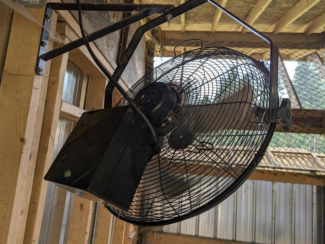
An initial "v1" of the 3-speed pull chain fan made "smart"
We took a simple "dumb" pull-string fan and:
- Added smart controls and integrated it with Home Assistant
- Added local logic to set the fan speed based on the reading from a local temperature sensor
- Allows the user to set the temperature thresholds for the fan speeds via Home Assistant
- Allows automations from Home Assistant to enable or disable the automatic temperature-based fan speed controls to respond to other environmental factors
- Allows the user to manually set the fan speed with a regular push button
- Stops the automatic fan speed controls when the user sets the fan speed explicitly through the push button
- Sets a user-configurable delay to re-enable automatic temperature-based controls
- Also allows the user to set the manual override to never automatically expire
...all with about $50 worth of hardware on top of the fan!
All of the code for this is up on Codeberg in my esphome-configs repo, and I definitely do encourage you again to check out 3ative's Ultimate Fan Project v4.0 as a key guide.


Comments
Respond to this post with an account on the Fediverse (like Mastodon).